The RP2040 and 2350 have an eight-element SIO (single-cycle IO) FIFO unit for inter-core communication. Multi-core real-time firmware can use this piece of integrated hardware to send signals between cores. The RP2xxx has two cores.
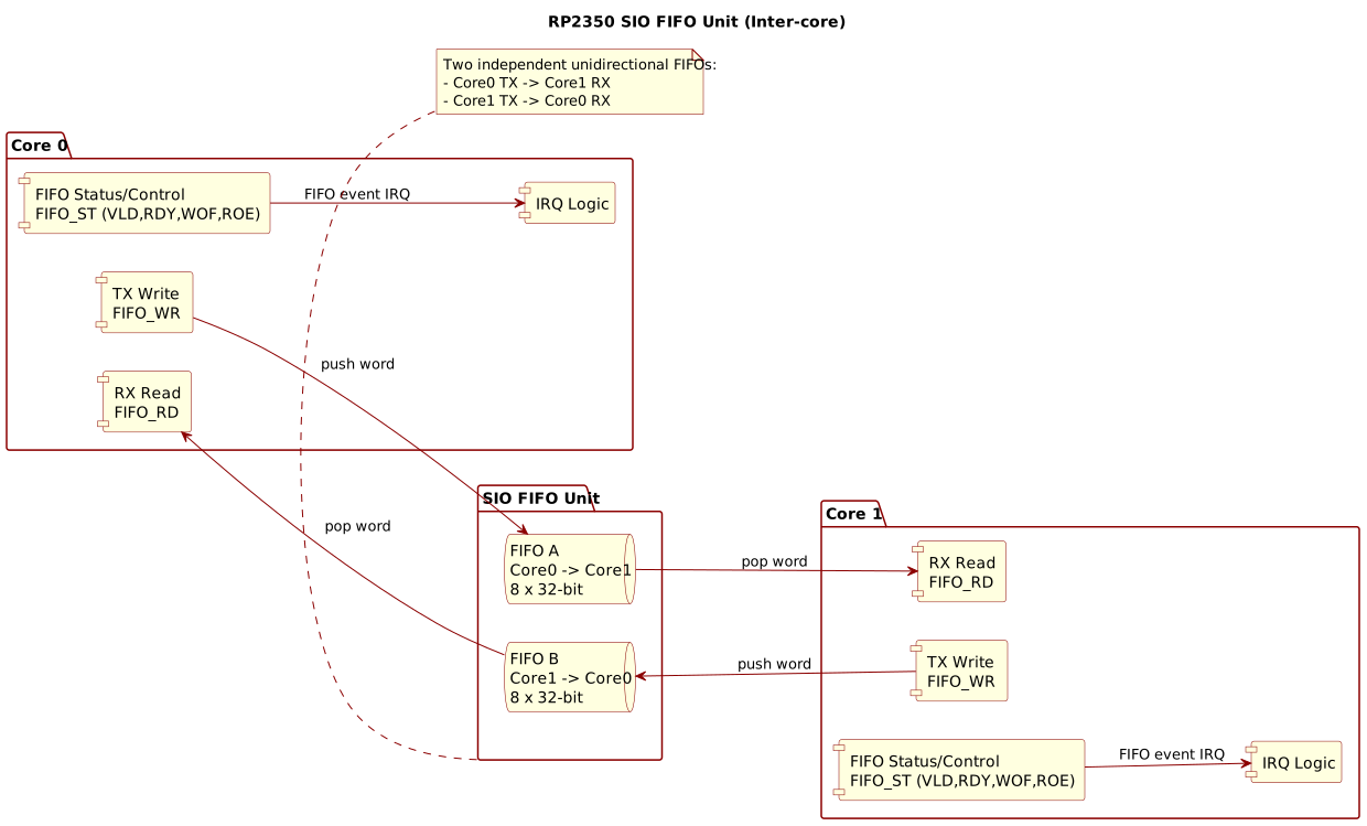
Figure 1: RP2350 SIO FIFO Unit for Inter-Core Communication
What you see in Figure 1 is a block diagram of the SIO FIFO unit. It consists of two FIFOs, one for each core. Each FIFO can hold up to eight 32-bit words. Core 0 pushes words to core 1, and vice versa. The FIFOs operate in a first-in-first-out manner, meaning that the first word pushed into the FIFO will be the first one popped out, allowing for orderly communication between the cores, ensuring that signals are processed in the order they were sent. The SIO FIFO unit also includes control logic for managing the FIFOs, such as handling interrupts when the FIFOs are full or empty, and ensuring that data is transferred correctly between the cores.
How best to use this peripheral block?
Brainstorming
One solution would be to use the SIO FIFO as a scheduler. The receiving core pops 32-bit signals one by one, and dispatches workers to access the other core’s results. That would work. However, it would require separate core-level synchronisation for access to shared resources, since the other core could be mutating a new set of results while the receiver core accesses the previous set.
One 32-bit datum counts for one signal with secondary synchronisation using cache-coherent mutexes or semaphores. Both cores operate independent memory caches. Doable but not ideal.
FOURCC Multi-Core FIFO
I had an idea.
The SIO itself works as a synchronisation mechanism. Why have another? Why not instead fold the conceptual inter-core signals together with some optional arguments? Signals may carry arguments: an integer or a float, perhaps even multiple arguments. The number of arguments is the signal “arity.” Arity-0 for signals without arguments, arity-1 for signals with one argument, and so forth. If the SIO carries both at the same time, secondary synchronisation primitives become redundant, or least less critical. The FIFO becomes the vehicle for signalling and data transfer.
First, always pop the FIFO under interrupts. That will keep the limited and fixed-size FIFO relatively clear and unblocked. When it becomes full, if it becomes full, the pushing core will block until the other core’s FIFO has space.
Then, interleave signal functors and signal arguments in the FIFO. Each multi-core signal encodes an arity: the number of signal arguments. Each signal becomes a triple: a functor code, an arity, and zero or more arguments.
It may not be practical for bulk exchanges, but in most multi-core FIFO use cases, signal transfers will be small and sporadic.
Four-Character Codes
A four-character 7-bit ASCII word could carry the signal “functor” and arity—lending the concept from functional and logic programming. Suppose that core 1 does some work. Perhaps it interacts with some external device, does some computation, and presents the results as a signal with some arguments to core 0.
Talking to an I2C peripheral might be one example. Core 1 arrives at a point in time where it wants to push \(\text{RDY}_1(x, y)\) to core 0, which will in turn record and publish to a USB communication endpoint, which also takes time to complete. This is just one of many possible scenarios, of course. The \(\text{RDY}_1\) signal has two arguments, arity of 2 words carrying two 32-bit floating-point numbers, for example.
Four 7-bit ASCII characters leaves four bits of a 32-bit word unused. Four bits can encode the \(0\le arity\le2^4-1\). In short, a 32-bit word passing through the SIO FIFO can simultaneously carry four 7-bit ASCII characters, good for a signal name, and an arity counter between zero and 15. Consecutive words can carry a signal’s additional 32-bit arguments, if any.
FOURCC from four characters
A simple macro translates four characters to a 32-bit word. See below. Some C compilers allow multi-character literals, but such is non-portable unlike the following implementation.
/*!
 * \brief Creates a FOURCC word from four 7-bit characters.
 *
 * \param a Most significant byte.
 * \param b Second byte.
 * \param c Third byte.
 * \param d Least significant byte.
 */
#define MULTICORE_FIFO_FOURCC(a, b, c, d) \
  (((uint32_t)((a) & 0x7f) << 24) | ((uint32_t)((b) & 0x7f) << 16) | ((uint32_t)((c) & 0x7f) << 8) | (uint32_t)((d) & 0x7f))
Note the 7-bit mask applied to each of the four characters. The eighth bit of each of the word’s four bytes will carry the encoded arity, hence masked out for the FOURCC.
Recovering the four characters from a FOURCC code is straightforward. See next. Given a multi-core FIFO word, it answers the FOURCC bits by masking out the arity bits. The result can compare by value with the results from the previous macro, e.g. in a switch statement.
/*!
 * \brief Masks out arity bits to extract the bare FOURCC code from a word.
 */
#define MULTICORE_FIFO_FOURCC_FROM_WORD(word) ((word) & 0x7f7f7f7fUL)
Again, the 7-bit mask applies to each of the four characters and ensures that the arity bits are not included in the recovered FOURCC code.
Arity and the FOURCC
Since arity lives in the most-significant bit position within each of the four bytes, its encoding and decoding requires some bit shifting. A simple helper macro can implement the functional mapping between \(bit\) position and amount of required shifting within a 32-bit word.
/*!
 * \brief Computes the shift that places arity bit \p bit into a FOURCC high-bit position.
 *
 * \param bit Arity bit index (0–3).
 *
 * \return Shift amount for bit \p bit.
 *
 * \details Places each arity bit at the high bit of one FOURCC character:
 *
 * - Bit 0 → position 7  (shift = 7)
 * - Bit 1 → position 15 (shift = 14)
 * - Bit 2 → position 23 (shift = 21)
 * - Bit 3 → position 31 (shift = 28)
 *
 * For arity 3 (0b011), bits 7 and 15 are set, yielding 0x00008080.
 */
#define MULTICORE_FIFO_FOURCC_ARITY_BIT_SHIFT(bit) ((((bit) & 0xf) << 3) + 7 - ((bit) & 0xf))
The translation applies to where an arity bit lives in its FIFO word and where it lives in the arity value, e.g. 7 and 0 respectively for the least-significant arity bit because \(7=0\times8+7-0\). Two mapping macros that apply the shift appear below.
/*!
 * \brief Encodes a 4-bit payload arity into the high-bit positions of a FOURCC word.
 *
 * \param arity Payload arity in words (0–15).
 *
 * \return A 32-bit mask to OR with a bare FOURCC code.
 */
#define MULTICORE_FIFO_WORD_FROM_ARITY(arity)                                                                                      \
  ((((arity) & 0x8) << MULTICORE_FIFO_FOURCC_ARITY_BIT_SHIFT(3)) | (((arity) & 0x4) << MULTICORE_FIFO_FOURCC_ARITY_BIT_SHIFT(2)) | \
   (((arity) & 0x2) << MULTICORE_FIFO_FOURCC_ARITY_BIT_SHIFT(1)) | (((arity) & 0x1) << MULTICORE_FIFO_FOURCC_ARITY_BIT_SHIFT(0)))

/*!
 * \brief Decodes the 4-bit payload arity from the high-bit positions of a FOURCC word.
 *
 * \param word A FOURCC word with arity encoded in its high bits.
 *
 * \return Payload arity in words.
 */
#define MULTICORE_FIFO_ARITY_FROM_WORD(word)                                                                                     \
  ((((word) >> MULTICORE_FIFO_FOURCC_ARITY_BIT_SHIFT(3)) & 0x8) | (((word) >> MULTICORE_FIFO_FOURCC_ARITY_BIT_SHIFT(2)) & 0x4) | \
   (((word) >> MULTICORE_FIFO_FOURCC_ARITY_BIT_SHIFT(1)) & 0x2) | (((word) >> MULTICORE_FIFO_FOURCC_ARITY_BIT_SHIFT(0)) & 0x1))
Pushing a FOURCC with Arity
Pushing a FOURCC and arity to the multicore FIFO then just becomes a
trivial mask and shift operation. Given some code and arity, for example
“RDY1” of arity 2, calling
multicore_fifo_push_fourcc_blocking(MULTICORE_FIFO_FOURCC('R', 'D', 'Y', '1'), 2U)
will push \(5244B931_{16}=52445931_{16}\lor00008000_{16}\) to the FIFO.
/*!
 * \brief Pushes the FOURCC functor word (with encoded arity) into the multicore FIFO.
 *
 * \param fourcc FOURCC code to push.
 * \param arity  Number of payload words to follow (0–15); encodes this value
 *               into the high bit of each FOURCC character.
 *
 * \warning Does \b not push payload words. The caller must push \p arity additional
 * words immediately after, creating a critical section that spans both operations.
 */
void multicore_fifo_push_fourcc_blocking(uint32_t fourcc, size_t arity) {
  multicore_fifo_push_blocking(MULTICORE_FIFO_FOURCC_FROM_WORD(fourcc) | MULTICORE_FIFO_WORD_FROM_ARITY(arity));
}
ASCII codes for R, D, Y and 1 are:
- R: 0x52
- D: 0x44
- Y: 0x59
- 1: 0x31
Notice that arity is encoded in the most significant bit of each character’s byte. So \(2\) shifts to bit 15, which is the most significant bit of the second character’s byte, resulting in \(00008000_{16}\).
Preemption
Pushing multiple words to the FIFO is not atomic, but pushing a single word is atomic. Therefore, pushing an initial FOURCC word with arity is atomic, but pushing the FOURCC’s arguments is not automatically atomic.
This only matters if FIFO pushes occur at interrupt time, which is not an uncommon use case. If an interrupt preempts a push sequence on the same core and the interrupt handler consequently pushes to the FIFO, the sequence can be interleaved with the interrupt’s push, resulting in a corrupted message.
To prevent this, interrupts should be disabled during the push sequence of a FOURCC with arguments, ensuring that the entire message is pushed atomically without interruption.
This leads to a multi-push critical section, which is a short but critical section of code where multiple pushes to the FIFO must be treated as an atomic operation. During this critical section, interrupts are disabled to prevent any interleaving of push operations that could lead to message corruption. Once the entire message has been pushed to the FIFO, interrupts are re-enabled, unless they were already disabled before entering the critical section.
/*!
 * \brief Pushes the FOURCC functor word and all payload words atomically.
 *
 * \param fourcc FOURCC code to push.
 * \param arity  Number of payload words (0–15).
 * \param args   Array of \p arity 32-bit payload words.
 *
 * \note Disables interrupts for the duration of the push to prevent
 * interleaving with interrupt-driven FIFO writes, ensuring the other
 * core receives a coherent, complete message.
 */
void multicore_fifo_push_fourcc_args_blocking(uint32_t fourcc, size_t arity, const uint32_t *args) {
  while (!multicore_fifo_wready()) {
    tight_loop_contents();
  }
  uint32_t status = save_and_disable_interrupts();
  multicore_fifo_push_fourcc_blocking(fourcc, arity);
  while (arity--) {
    multicore_fifo_push_blocking(*args);
    args++;
  }
  restore_interrupts(status);
}
The initial “while not FIFO write ready” tight loop mitigates the time spent blocking with interrupts disabled. It does not entirely prevent such, but does reduce the likelihood. Imagine scenarios where interrupt handlers push to the SIO as well. Waiting for “write ready” starts the critical section with interrupts disabled with at least one element of the FIFO available. A very small preemption window still exists in-between the tight while loop and disabling interrupts; an interrupt could trigger and start filling the FIFO so that the first FOURCC-arity push inside the critical section has to block.
The window is small however, and the design supposes that the other core services the FIFO at interrupt time in order to minimise latency in its partner. More on that later.
Popping
Popping the FIFO is not quite as simple as pushing, but still straightforward. The receiving core pops the FIFO under interrupts, and decodes the FOURCC and arity from the popped word. The receiving core can then pop the appropriate number of arguments from the FIFO based on the decoded arity.
It requires a simple structure to hold the decoded FOURCC and arity, plus any extra arguments, and a simple function to perform the decoding.
/*!
 * \brief Holds the decoder state and buffer for one FOURCC message.
 */
struct multicore_fifo_fourcc {
  /*!
   * \brief Decoder state: counts words received so far for the current message.
   *
   * \details The arity bits in the first functor word set the expected total.
   * The field increments as each word arrives:
   *
   * - 0: idle, ready to accept a new functor word.
   * - 1 to total−1: accumulating payload words.
   * - equals total: message complete, ready to dispatch.
   */
  size_t arity;

  /*!
   * \brief Message buffer: words[0] carries the functor; words[1..arity] carry the payload.
   */
  uint32_t words[16];
};
Filling the FOURCC structure with words from the FIFO
This requires some subtle logic to fill the structure correctly as words are popped asynchronously from the FIFO. The design of the following function aims to incrementally decode a receiver core’s SIO FIFO using the FOURCC-arity law. It runs at interrupt time, buffering the incoming words as and when they arrive.
Note that words belonging to the same FOURCC-arity encoded signal may, or may not, arrive concurrently. It is possible, albeit rare, that a receiving core could empty its FIFO before a sending core completes a multi-word push sequence; this is true even if the sequence disables interrupts, because the SIO hardware logic makes no guarantees about delivery beyond limits of a 32-bit word. The design overcomes this by allowing for any amount of de-synchronisation between cores.
/*!
 * \brief Feeds one word into the FOURCC decoder.
 *
 * \param fourcc Decoder state to update.
 * \param word   Next word from the FIFO. Supply the functor word first;
 *               subsequent calls deliver payload words.
 *
 * \return 0 when the decoder assembles a complete message; negative while
 *         still accumulating words.
 */
int multicore_fifo_fill_fourcc(struct multicore_fifo_fourcc *fourcc, uint32_t word) {
  fourcc->words[fourcc->arity] = word;
  const size_t arity = multicore_fifo_fourcc_arity(fourcc);
  int rc = fourcc->arity - arity;
  if (rc < 0) {
    fourcc->arity++;
  } else {
    fourcc->arity = 0U;
  }
  return rc;
}
It accumulates words until the number of words match the expected arity. The arity field acts as the FIFO decoder’s current state. Each core’s FOURCC structure operates an arity counting state machine.
- When the arity field is \(0\), the FIFO is empty and ready to receive a new FOURCC code.
- When the progressive arity is between \(1\) and the total arity of the initial FOURCC code, the FIFO is in the process of receiving a FOURCC code and its associated data.
- Whenever the arity field matches the expected arity of the FOURCC code, the FIFO has received a complete FOURCC code and its associated data, and is ready to be processed.
How to Use
GitHub contains a working example.
Core 0 Sets Up Its SIO Interrupt Handler
The example is very simple. Core 0 sets up its SIO interrupt handler after draining the core-0 FIFO. It then launches core 1 and enters an infinite loop. All the work by core 0 runs at interrupt time; see the SIO Interrupt Handler section below.
int main() {
  stdio_init_all();

  multicore_fifo_drain();
  irq_set_exclusive_handler(SIO_FIFO_IRQ_NUM(0), core0_sio_irq);
  irq_set_enabled(SIO_FIFO_IRQ_NUM(0), true);
  multicore_launch_core1(core1_entry);

  for (;;) {
    tight_loop_contents();
  }
}
The drain proves necessary because the SIO FIFO is not guaranteed to be empty at reset. It may contain some random data, which could cause the interrupt handler to misinterpret it as a valid message. Draining ensures that the interrupt handler starts with a clean slate.
Core 1 Pushes Signals to Core 0
Core 1 pushes a zero-arity “COR1” message, then three consecutive delayed “TICK” messages with the current microsecond timestamp as an argument, and finally a zero-arity “DEAD” message before halting itself.
static void core1_entry(void) {
  multicore_fifo_push_fourcc_blocking(MULTICORE_FIFO_FOURCC('C', 'O', 'R', '1'), 0);
  for (size_t count = 3U; count; count--) {
    sleep_ms(1000);
    multicore_fifo_push_fourcc_arg_blocking(MULTICORE_FIFO_FOURCC('T', 'I', 'C', 'K'), time_us_32());
  }
  multicore_fifo_push_fourcc_blocking(MULTICORE_FIFO_FOURCC('D', 'E', 'A', 'D'), 0);
}
SIO Interrupt Handler
The interrupt handler pops and fills the FOURCC structure which decodes the stacked words one by one.
static void core0_sio_irq(void) {
  while (multicore_fifo_rvalid()) {
    if (multicore_fifo_pop_fourcc_blocking(&core0_fourcc) == 0) {
      const uint32_t cccc = multicore_fifo_fourcc_peek(&core0_fourcc);
      const size_t arity = multicore_fifo_fourcc_arity(&core0_fourcc);
      const uint32_t *const args = multicore_fifo_fourcc_args(&core0_fourcc);

      printf("Received FOURCC by core %u: %c%c%c%c with arity %zu and args:",
             /* by core */ get_core_num(),
             /* first FOURCC */ (cccc >> 24) & 0xFF,
             /* second FOURCC */ (cccc >> 16) & 0xFF,
             /* third FOURCC */ (cccc >> 8) & 0xFF,
             /* fourth FOURCC */ cccc & 0xFF, arity);
      for (size_t i = 0; i < arity; ++i) {
        printf(" 0x%08x", args[i]);
      }
      printf("\n");

      switch (cccc) {
      case MULTICORE_FIFO_FOURCC('C', 'O', 'R', '1'):
        switch (arity) {
        case 0:
          printf("Core 1 has started.\n");
        }
        break;
      case MULTICORE_FIFO_FOURCC('T', 'I', 'C', 'K'):
        switch (arity) {
        case 1:
          printf("Core 1 ticked at %u microseconds.\n", args[0]);
        }
        break;
      case MULTICORE_FIFO_FOURCC('D', 'E', 'A', 'D'):
        switch (arity) {
        case 0:
          printf("Core 1 is dead.\n");
          multicore_reset_core1();
          multicore_launch_core1(core1_entry);
        }
        break;
      default:
        printf("Unknown FOURCC received.\n");
      }
    }
  }
  multicore_fifo_clear_irq();
}
The switch implementation matches the four-character code and the arity. This is proper since the same FOURCC could have various alternative arities.
Serial Monitor
Output on the serial monitor appears as follows:
Received FOURCC by core 0: COR1 with arity 0 and args:
Core 1 has started.
Received FOURCC by core 0: TICK with arity 1 and args: 0x000f44ea
Core 1 ticked at 1000682 microseconds.
Received FOURCC by core 0: TICK with arity 1 and args: 0x001e8737
Core 1 ticked at 2000695 microseconds.
Received FOURCC by core 0: TICK with arity 1 and args: 0x002dc978
Core 1 ticked at 3000696 microseconds.
Received FOURCC by core 0: DEAD with arity 0 and args:
Core 1 is dead.
This sequence repeats indefinitely because core 0 resets and relaunches core 1 after it sees a “DEAD” signal from core 1.
This is the primary take away: the SIO FIFO carries signals with variable arguments. The arguments need to be 32 bits in size, or at least padded to 32 bits. The argument or arguments flexibly carry data along with a signal through a core-synchronised hardware unit.
Final Thoughts
Is this a reasonable solution to an inter-core communication protocol? It is one of many, not the ultimate solution per se. One size does not fit all. Nevertheless, the implementation is super simple. That can be an advantage, especially for interactions between cores where a typical design would prefer performance over sophistication. Speed is the essence.
There is a caveat when pushing to a FOURCC structure at interrupt time when there are more than zero arguments, i.e. non-zero arity. Multi-core FIFO pushes are atomic, but multiple multi-core FIFO pushes are not atomic. That only means that signals with arity require disabled interrupts in such scenarios. FIFO push sequences are short but critical sections.
This approach does not preclude overlapping bulk transfer schemes where the multi-core FIFO carries some arity-message, prompting the other core to access some other RAM-based shared resource, a ring buffer or queue. The other core can apply mutual-exclusion primitives to synchronise access to the resource after popping the appropriate message.