This article describes controlling DC motors with the L298 dual H-bridge driver and a Raspberry Pi, using embedded Prolog for motion planning. It covers GPIO pin control, interrupt-driven PWM generation, and the hardware and software required for precise motor control in resource-constrained embedded systems.
Also available as PDF.
Introduction
The L298 by STM [1] drives a pair of DC motors either clockwise or anticlockwise.
How It Works
The L298 integrated circuit has six transistor-transistor logic (TTL) inputs, three for each motor.
- \(In_1\), \(In_2\) and \(En_A\) for motor A.
- \(In_3\), \(In_4\) and \(En_B\) for motor B.
The \(In\) signals set the bridge state when \(En\) is high. Driving \(In_1\) high turns the motor clockwise, or “forward.” Driving \(In_2\) high turns it anticlockwise, or “reverse.” Likewise, for \(In_3\) and \(In_4\) at motor B. It goes without saying that such labels only have a nominal meaning. “Forward” could actually equate to “reverse,” depending on electrical wiring and mechanical factors; dual motors might drive opposing axles, for instance, hence one motor will turn in the opposite direction from the axle’s perspective.
The \(En\) inputs typically receive a pulse-width modulated signal that selects the rotation speed of the DC motor based on its duty cycle. Strictly speaking, \(En\) does not need to receive the PWM signal; it could also be the \(In_x\) signals. The L298 does not care which side of the bridge does the pulsing.
The input signals \(In_i|i\in 1..4\) and \(En_e|e\in A,B\) are input to the motor driver circuitry. These signals are output from the motor control system. One man’s input is another man’s output.
Hence, to control two bidirectional DC motors using an L298, the embedded control firmware must modulate six digital outputs, three for each motor. At least one of the digital outputs must have a pulse-width modulated signal, ideally driven directly by hardware or at least by interrupt-driven high-resolution timer-based software.
See Figure 1.
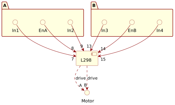
Figure 1: L298 component schematic. The L298 drives two motors, A and B. Three digital signals control the A motor; another three for the B motor. Pin numbers reflect the 20-pin PowerSO-20 (P) package, L298P. The signal order echoes the pin order, low to high.
Table 1 summaries the L298 inputs and their corresponding function.
| Inputs | Function |
|---|---|
| \(V_{en}=H\); \(C=H\); \(D=L\) | Forward |
| \(V_{en}=H\); \(C=L\); \(D=H\) | Reverse |
| \(V_{en}=H\); \(C=D\) | Fast motor stop |
| \(V_{en}=L\); \(C=X\); \(D=X\) | Free-running motor stop |
So far, so good. In an ideal world, hardware-clocked pulse-width modulators drive the signals in real time.
Pseudo-Real Time
However, suppose that dedicated hardware for an L298 application does not exist. What happens if software is the only option? To make an embedded developer’s life even more complicated, consider that the operating system does not have real-time capabilities, e.g. standard Linux without real-time patches. Software solutions to such hardware problems have notoriously poor outcomes without some form of “hard” real-time capability.
A reasonable compromise does exist.
Assuming that the embedded target is a Raspberry Pi running Linux kernel
version \(6\) or later, the L298 motor driver can be controlled using only
raw GPIO pins. The next section describes how to use the pwm-gpio
driver to generate pulse-width modulated signals for motor control,
allowing for reasonably-precise control of the motors by leveraging
high-resolution timers and interrupt-driven PWM generation.
Bit Bashing GPIO at Interrupt Time
The stock Linux kernel version \(6\) equips a pwm-gpio driver
[2]. Once configured, it creates a pseudo-PWM driven
by a high-resolution interrupt-driven kernel timer. This is as close to
a hardware timer without the hardware that Linux can achieve. The CPU
becomes the hardware driving the pulses. This is not “bit bashing” in
the classic sense. In the old days, CPU instructions were carefully
crafted to generate signals without interrupts; that probably still
happens for trivial cases. The PWM-GPIO driver, however, takes only a
small slice of CPU time to generate a PWM signal.
Interrupts drive kernel timers. So the CPU, or its multi-cores, can do other work in-between interrupts. The PWM-GPIO driver is not a real-time solution, but it is good enough for many applications, including motor driving since the fidelity of the output is not extreme.
Hardware Attached on Top
Take a concrete example. Table 2 describes motor “Hardware Attached on Top” (HAT) of a Raspberry Pi. The HAT expansion board equips an L298P from STM wired to the Pi’s GPIO pins. These are the Broadcom (BCM) system-on-chip pin designations, not the physical board pin header numbers.
| L298 | A | B |
|---|---|---|
| \(En_{A,B}\) | GPIO4 | GPIO17 |
| \(In_{1,3}\) | GPIO14 | GPIO27 |
| \(In_{2,4}\) | GPIO15 | GPIO18 |
How to set up the Linux kernel to handle these GPIO signals?
Device tree configuration
On Raspberry Pi, add the following to the config.txt file
[3] that lives in /boot/firmware.
# | L298  | A      | B      |
# |-------|--------|--------|
# | EnA,B | GPIO4  | GPIO17 |
# | In1,3 | GPIO14 | GPIO27 |
# | In2,4 | GPIO15 | GPIO18 |
#
gpio=14,15,27,18=op,dl
dtoverlay=pwm-gpio,gpio=4
dtoverlay=pwm-gpio,gpio=17
These kernel configuration lines export the L298 input signals as GPIO
outputs. The pwm-gpio driver captures GPIO lines 4 and 17 as PWM outputs.
After a reboot, user-land GPIO reports the following. Details elided.
$ gpioinfo 0
gpiochip0 - 58 lines:
        line   4:      "GPIO4" "pwm_gpio@4"  output  active-high [used]
        line  14:     "GPIO14"       unused  output  active-high
        line  15:     "GPIO15"       unused  output  active-high
        line  17:     "GPIO17" "pwm_gpio@11" output  active-high [used]
        line  18:     "GPIO18"       unused  output  active-high
        line  27:     "GPIO27"       unused  output  active-high
At this point, the kernel is ready to operate the L298. See Fig. 2. It depicts the resulting line and channel configuration. The L298 enable lines (4 and 17) are driven by the PWM-GPIO driver.
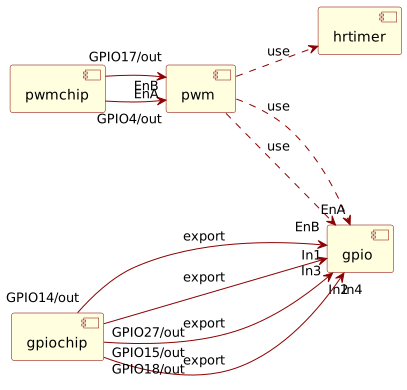
Figure 2: PWM GPIO driver. The L298 enable lines are driven by the PWM-GPIO driver. The L298 input signals export as GPIO outputs.
The GPIO lines and PWM channels exist as kernel-space objects only. Two PWM GPIO pseudo-chips lock the “enable” lines, driving pulse-width modulation using high-resolution kernel timers. The L298 input signals export as GPIO outputs.
The next problem is connecting the kernel to user space.
User-Land Control
More than one method exists to control the L298 from user-land. One way
is to manipulate the GPIO lines using the libgpiod library [4]
to set up motor-direction control; it indirectly configures and
manipulates GPIO lines via ioctl calls operating on the underlying
character-device files. Trouble is, at the time of writing, Linux does
not equip similar support for pulse-width modulation channels.
The more usual, albeit generally deprecated, way is to use the Linux kernel’s \(sysfs\) pseudo-file system.
Let’s be naughty.
System’s File System
Linux kernels publish access points to kernel objects by mounting a
pseudo-file system called \(sysfs\). It typically mounts off the root at
/sys. Within its directory tree, the kernel exposes GPIO lines and PWM
channels as files. User-land processes read and write these files to
configure and manipulate the kernel objects. Very basic and simple, but
it works. The kernel does the heavy lifting—configuring and
manipulating the GPIO lines and PWM channels. User-land processes just
read and write files.
Why naughty? Linux deprecates its use. Not all kernels build with it installed; the kernel build requires configuring for \(sysfs\). Fortunately, most still do. And, currently, this includes the Raspberry Pi’s standard Linux kernel.
Pure Logic
Since the \(sysfs\) approach amounts to file-based open, read, write and close operations; the coding of the interface can be in any language, including high-level languages.
Why not Prolog? It’s a personal favourite, for sure. But there’s more. Prolog has certain qualities for explanation and understanding. It helps the developer focus on relations between behavioural components only, with much less mind clutter and contention with technicalities when compared to most other languages.
- Straightforward goal-oriented logic syntax.
- Backtracking to find the truth.
- Light and flexible type system.
- Arbitrary tabling for performance optimisations.
Discovering logic without distraction: that’s its superpower. It is rightly called the grandfather of artificial intelligence languages.
System Pseudo-File Predicates
I prototyped a Prolog package for controlling GPIO lines and PWM channels via the \(sysfs\) pseudo-file system. The package provides a set of predicates that abstract the underlying file operations, allowing users to manipulate GPIO and PWM objects in a more declarative manner.
The pack includes predicates for exporting and unexporting GPIO lines, setting their direction, reading and writing values, as well as configuring PWM channels. By using these predicates, developers can easily control hardware components without needing to deal with low-level file operations directly.
Importantly, the predicates handle ‘delayed manifestations’ of the kernel objects. For example, when a GPIO line is exported, the kernel will take some time, relatively, to create the corresponding files in the appropriate \(sysfs\) directory. The predicates include a mechanism to wait for these files to become available before proceeding with further operations, ensuring that user-land processes can interact with the hardware reliably without encountering race conditions.
Track Control
So much for the theory. Let’s get down to the nitty-gritty of controlling a pair of DC motors with the L298. The following sections describe the hardware and software setup for controlling the motors, including the GPIO pin assignments, PWM configuration, and direction-control logic. The goal is to provide a practical implementation of the concepts discussed earlier, enabling precise motor control for robotic applications.
Imagine a single L298 driving a pair of DC track motors on some tracked vehicle. The port-side track of the vehicle is driven by one H-bridge, while the other H-bridge drives the starboard-side track. The L298 has two enable inputs, one for each H-bridge, which control the speed of each track motor using pulse-width modulation (PWM). Two input signals per H-bridge control the direction of each track motor.
Circuit Board
First, define the circuit board’s six connections to the L298. See Fig.
3. This is the base knowledge of the system. The
following Prolog facts define the six GPIO lines connected to the
L298’s inputs and enables. The pwm_line/3 predicate defines the PWM
lines1 for the enable inputs, while the gpio_line/3
predicate defines the GPIO lines for the direction inputs.
% PWM signals for the L298 motor driver. These signals are used to
% enable the motors and control their speed via PWM.
pwm_line(en(a), 'pinctrl-bcm2711', 4).
pwm_line(en(b), 'pinctrl-bcm2711', 17).

% GPIO signals for the L298 motor driver. These signals are used to
% control the direction of the motors by setting the appropriate GPIO
% pins high or low.
gpio_line(in(1), 'pinctrl-bcm2711', 14).
gpio_line(in(2), 'pinctrl-bcm2711', 15).
gpio_line(in(3), 'pinctrl-bcm2711', 27).
gpio_line(in(4), 'pinctrl-bcm2711', 18).
The first argument specifies the symbolic term assigned to the signal; these terms align with the L298 signal names. The second argument is the GPIO controller name, and the third is the GPIO line offset. The facts appear as two separate groups because \(sysfs\) exposes the PWM and GPIO lines in different directories, each accessing different kernel interfaces.
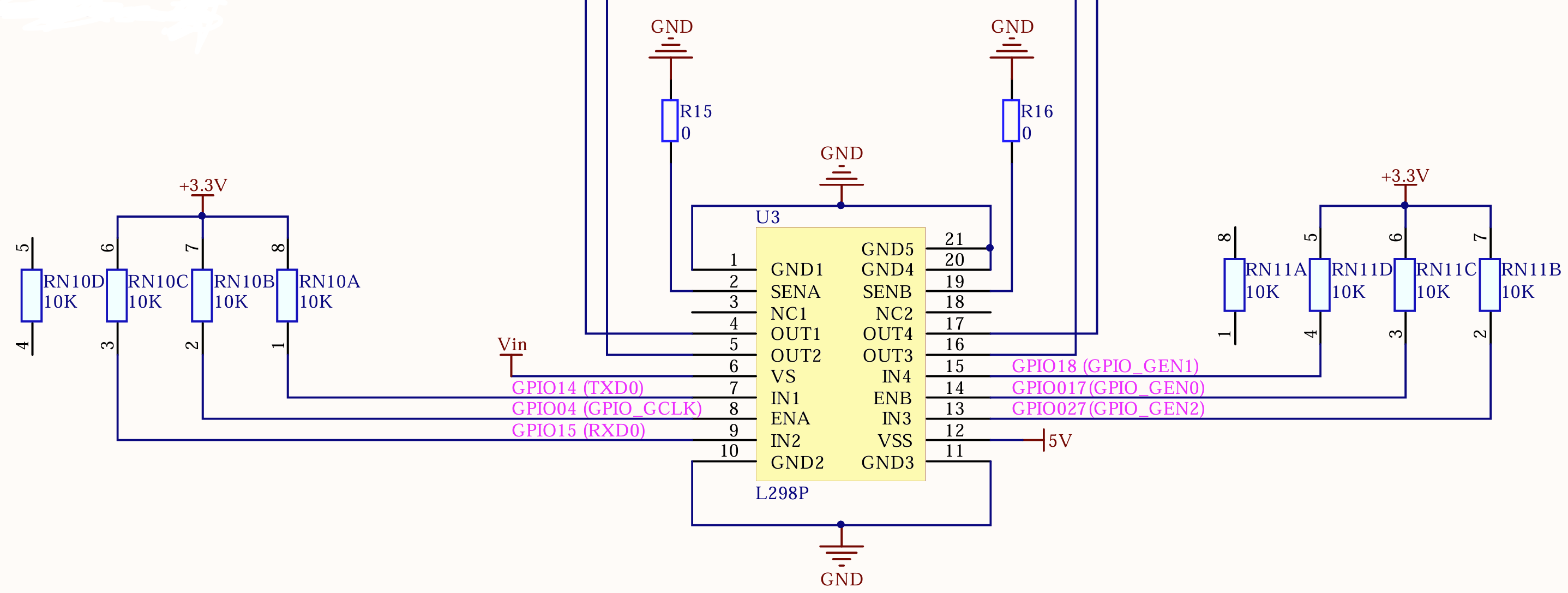
Figure 3: Circuit board. The L298 connects to the Raspberry Pi’s GPIO lines via a circuit board. The enable lines are driven by the PWM-GPIO driver, while the input signals are exported as ordinary run-of-the-mill GPIO outputs.
Pulse-Width Modulation for the enable lines
Next, set up the two PWM channels for the L298’s enable inputs. This
involves taking a signal’s label and offset, finding the corresponding
GPIO chip, and then finding the PWM chip associated with that GPIO chip.
The pwm/2 predicate accomplishes this task; see below. The last clause
of the predicate performs the export of the PWM channel to the sysfs
interface, deriving a unique Chip(Chan) term for addressing PWM-GPIO
channels.
pwm(Signal, PWM) :-
    pwm_line(Signal, Label, Offset),
    gpiochip_by_label(Label, GPIOChip),
    sysfs_gpiochip_offset_of_pwmchip(GPIOChip, Offset, PWMChip),
    % Assume that the PWM export is always channel 0 for the given GPIO pin.
    % This is a simplification and may need to be adjusted based on the actual
    % hardware configuration.
    sysfs_pwm(PWMChip, 0, PWM).

gpiochip_by_label(Label, Chip) :- once(sysfs_gpiochip_read(label, Chip, Label)).

% Set the PWM period to 50 Hz for all PWM channels used in this
% configuration.
:- forall(pwm(_, PWM), sysfs_pwm_write(PWM, period(50, hz))).
Finding a chip by its label works by non-deterministically searching the
\(sysfs\) GPIO chips for a match. The sysfs_gpiochip_read/3 predicate
reads the label of each GPIO chip and unifies it with the provided
label. The once/1 predicate ensures that only the first matching chip
is returned.
The sysfs_pwm_write/2 predicate sets the PWM period to 50 Hz for both
of the PWM channels found by the pwm/2 predicate. This frequency is
suitable for controlling motor speed.
GPIO for the input lines
This proves easier.
gpio_line(Signal, Line) :-
    gpio_line(Signal, Label, Offset),
    gpiochip_by_label(Label, Chip),
    sysfs_gpio_line(Chip, Offset, _, Line).
The gpio_line/2 predicate finds the GPIO line associated with a given
signal. It first retrieves the label and offset of the GPIO line from
the gpio_line/3 facts; then finds the corresponding GPIO chip using
the gpiochip_by_label/2 predicate. Finally, it retrieves the GPIO’s
\(Line\) term using the sysfs_gpio_line/4 predicate.
The \(Line\) term is an atom that uniquely identifies the GPIO line in the
\(sysfs\) interface, allowing for easy manipulation of the GPIO pin’s
state (high or low) to control the direction of the motors. Its export
number, ignored by the _ above, derives from the GPIO chip’s “base”
and line offset.
Ahead and Astern
Let’s declare what forward and reverse mean. It depends on the wiring of
the motors. The following facts define the forward mappings; then the
reverse mappings derive from them. The ahead/4 predicate defines the
forward direction for each motor, while the astern/4 predicate defines
the reverse direction by swapping the GPIO pins used for forward and
reverse.
% Define the forward mappings for the motors. These imply the reverse
% mappings as well, since reversing a motor simply swaps the GPIO pins
% used for forward and reverse.
ahead(port, b, 3, 4).
ahead(starboard, a, 2, 1).

% Reverse uses the same En signal but swaps the GPIO pins. For motor A,
% reverse means setting GPIO pin 2 high and GPIO pin 1 low, while for
% motor B, reverse means setting GPIO pin 4 high and GPIO pin 3 low.
astern(Abeam, En, InLo, InHi) :- ahead(Abeam, En, InHi, InLo).
Ahead on the left (port) side requires setting GPIO pin 3 high and GPIO
pin 4 low, while ahead on the right (starboard) side requires setting
GPIO pin 2 high and GPIO pin 1 low. The ahead/4 predicate captures
these relationships. Signal \(En(B)\) is the enable signal for the
port-side motor, while \(En(A)\) is the enable signal for the
starboard-side motor. The GPIO pins are specified in the order of high
and low signals required to achieve forward or reverse motion.
This design allows for easy control mapping of the motors by simply specifying the desired “ahead” configuration and the corresponding enable signal. Astern falls out naturally.
Bearing
Four natural “bearings” exist for a tracked vehicle: ahead, astern, port, and starboard. They combine to form the four diagonal bearings: port-ahead, starboard-ahead, port-astern, and starboard-astern. Note that ‘turning left’ or ‘turning right’ is not a natural bearing; it is a combination of two bearings. Right turn is a combination of port-ahead and starboard-astern, while left turn is a combination of starboard-ahead and port-astern. Hence the strange ship terminology of “ahead” and “astern” for forward and reverse, respectively. Ahead and astern describe what the motors do, not necessarily the direction of vehicular motion. The vehicle may be moving forward while the motors are running astern, for example, when the vehicle is sliding down a hill.
The following facts define the four natural bearings and their corresponding motor control configurations. The logic also addresses the “stop” condition, which can be either \(slow\) or \(fast\). Slow means switching off the DC current, while fast means switching on the current to both sides of the H-bridge to brake the motors.
bearing(ForeAft, Abeam) :-
    bearing(ForeAft, Abeam, _, InHi, InLo),
    !,
    bearing(InHi, InLo, 1, 0).
bearing(stop(slow), Abeam) :-
    !,
    bearing(ahead, Abeam, _, InHi, InLo),
    bearing(InHi, InLo, 0, 0).
bearing(stop(fast), Abeam) :-
    bearing(astern, Abeam, _, InHi, InLo),
    bearing(InHi, InLo, 1, 1).

bearing(InHi, InLo, Hi, Lo) :-
    gpio_line(in(InHi), LineHi),
    gpio_line(in(InLo), LineLo),
    % Write the low signal first to avoid stopping the motor driver.
    % Let it transition from high to low before setting the other line high.
    sysfs_gpio_write(LineLo, value(Lo)),
    sysfs_gpio_write(LineHi, value(Hi)).

bearing(ahead, Abeam, En, InHi, InLo) :- ahead(Abeam, En, InHi, InLo).
bearing(astern, Abeam, En, InHi, InLo) :- astern(Abeam, En, InHi, InLo).
The four-arity bearing/4 actually performs the work of setting the
GPIO lines for the motors. It takes \(In(Hi, Lo)\) specifying the high and
low L298 inputs to re-configure, and \(Hi, Lo\) specifying the values to
write to those lines, respectively. The predicate first retrieves the
corresponding GPIO lines using the gpio_line/2 predicate, then writes
the low value first to avoid stopping the motor driver, followed by
writing the high value. A motor will briefly transition through a
slow-stop state, i.e., free-wheeling, when changing direction.
So far, the logic concerns direction setting only. It does not yet address speed control.
Throttle Control
Throttle control is the next step. The L298’s enable inputs control the speed of the motors using pulse-width modulation (PWM). The following predicates define the throttle control logic for the motors.
throttle(Abeam, Fract) :- ahead(Abeam, En, _, _), en(En, Fract).

%! en(En, Fract) is det.
%
% Controls an L298 enable pin by fractional duty cycle. The En signal is
% associated with a specific motor (A or B), and the Fract parameter
% specifies the duty cycle as a fraction (0 to 1). A positive Fract
% value enables the motor with the specified duty cycle, while a
% non-positive value disables the motor.
%
% @arg En The enable signal for the motor (a or b).
%
% @arg Fract The fractional duty cycle (0 to 1) for the PWM signal
% controlling the motor speed. A value of 0 or less disables the motor.
en(En, Fract) :- pwm(en(En), PWM), write_en(PWM, Fract).

write_en(PWM, Fract), Fract > 0 =>
    sysfs_pwm_write(PWM, duty_cycle(Fract, fract)),
    sysfs_pwm_write(PWM, enable(1)).
write_en(PWM, Fract), Fract =< 0 =>
    % Assume that disabling the PWM signal lowers the Enable pin, effectively
    % stopping the motor regardless of its Input pins.
    sysfs_pwm_write(PWM, enable(0)).
How it works
Calling
throttle(port, 0.5)sets the port-side motor to run at 50% speed, whilethrottle(starboard, 1.0)sets the starboard-side motor to run at full speed.A call to
throttle(port, 0)orthrottle(starboard, 0)stops the respective motor.
This makes an important assumption: that the PWM-GPIO driver lowers the enable pin when the PWM signal is disabled, irrespective of the input pins. This assumption is based on the typical behaviour of PWM drivers, but it may vary depending on the specific hardware and driver implementation.
Abstract Steering
Putting it all together, the following predicate provides an abstract interface for steering the tracks using the bearing and throttling layers.
%! steer(Abeam, Fract) is det.
%
% Steering combines throttle and bearing to control the direction and
% speed of the motors. The steer predicate takes an Abeam (port or
% starboard) and a Fract value, which determines the throttle level and
% direction of the motor. If Fract is positive, it steers ahead; if
% negative, it steers astern.
%
% @arg Abeam The side of the vehicle (port or starboard) to steer.
%
% @arg Fract The fractional throttle value, where positive values
% indicate forward motion and negative values indicate reverse motion.
% The value is clamped to a minimum of 0.1 for forward and a maximum of
% -0.1 for reverse to prevent stalling or abrupt stops.
steer(Abeam, Fract) :-
    steer(Fract, ForeAft, Fract1),
    throttle(Abeam, Fract1),
    bearing(ForeAft, Abeam).

steer(Fract, ahead, Fract) :- Fract >= 0.1, !.
steer(Fract, astern, -Fract) :- Fract =< -0.1, !.
steer(_, stop(slow), 0).
How it works
Calling
steer(port, 0.5)sets the port-side motor to run ahead at 50% throttle, whilesteer(starboard, -0.5)sets the starboard-side motor to run astern at 50% throttle.
The steer/2 predicate abstracts the details of throttle and bearing
control, allowing for a more intuitive interface for controlling the
vehicle’s movement.
Joystick Controller
If the vehicle equips a joystick controller, how does the joystick’s X and Y values translate into throttle and bearing commands for the motors? The following equations map from joystick input to motor control.
\[\begin{aligned} steer_{port} &= X - Y \\ steer_{starboard} &= -X - Y \end{aligned}\]
Positive X values correspond to rightward movement, while negative X values correspond to leftward movement. Negative Y values correspond to forward movement, while positive Y values correspond to backward movement. The port throttle \(steer_{port}\) is calculated as the difference between the X and Y values, while the starboard throttle \(steer_{starboard}\) is calculated as the negative sum of the X and Y values. These throttle values can be broadcasted to the respective channels for steering.
Conclusions
Latency is important when driving motors. Signals come from a controller, typically a joystick. Events from the operator’s joystick pass through the external interface, typically USB. These enter the kernel and pass to user space. They are processed by the control software, which generates the appropriate motor drive signals. These are sent back to the kernel and then to the GPIO pins. This adds up to a significant amount of latency, which can be detrimental to the operator’s experience. Of course, the hardware itself also adds latency, but the software control loop is often the main contributor. Ideally, the operator should feel that the motors respond quickly and smoothly to their inputs, without noticeable lag. To achieve this, the software control loop must be optimised for low latency.
Optimisation strategies include:
- Using a real-time operating system (RTOS) or real-time extensions to Linux to reduce scheduling latency.
- Minimising the number of context switches and system calls in the control loop.
- Using hardware PWM support if available, to offload the timing-critical signal generation from the CPU.
- Prioritising the control process to ensure it gets CPU time when needed.
References
Lines allocated to the software PWM↩︎